Rs. 191.00
Special Features
Fitting Instructions
Finish
Rs. 399.00
Non-Staining & Non-Marring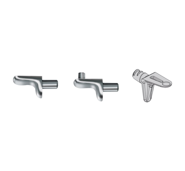
Rs. 11,275.00
Easy to use with elegant looks for wood or glass shelves.
Requires ø5mm drill to fix.
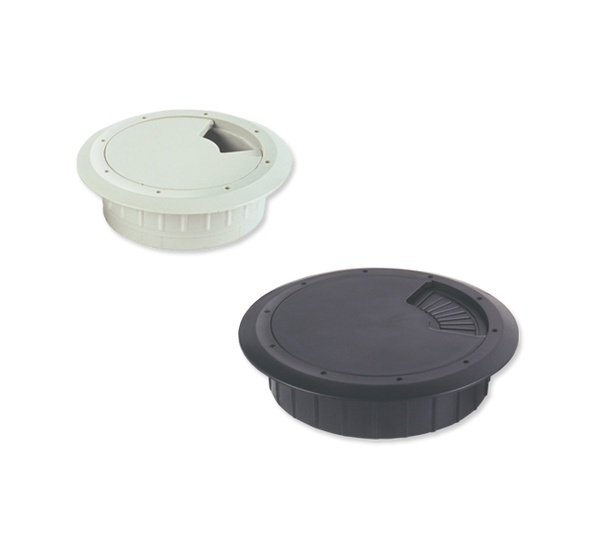
| Model | Code | Type | Application | Load Capacity | Size | Finish |
| Cabinet Shelf Support 1 Lug | CSS1 | 1 lug | Glass Shelves | 10kg/pc | Small | Chrome Plated |
| CSS1N | 1 lug | Wooden Shelves | 15 kgs | Regular | Nickel Plated | |
| Cabinet Shelf Support 2 Lug | CSS2 | 2 lugs | Wooden Shelves | 10 kg/pc | Regular | Chrome Plated |
Rs. 41.00
Rs. 186.00
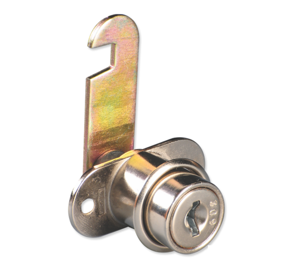
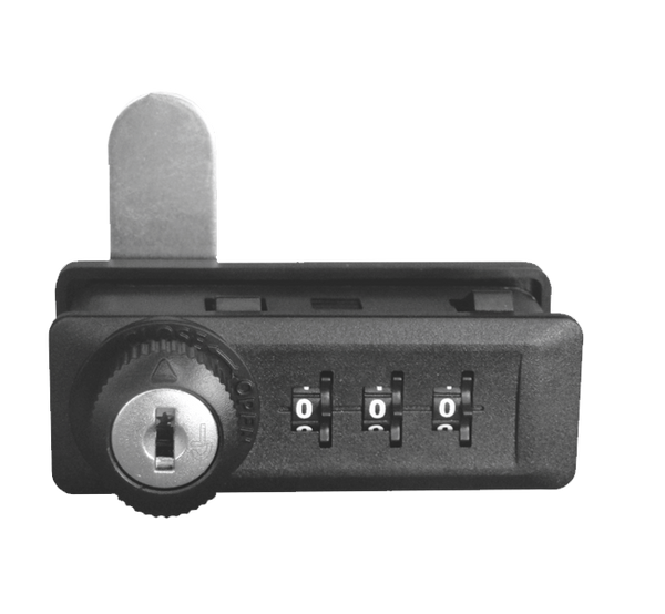
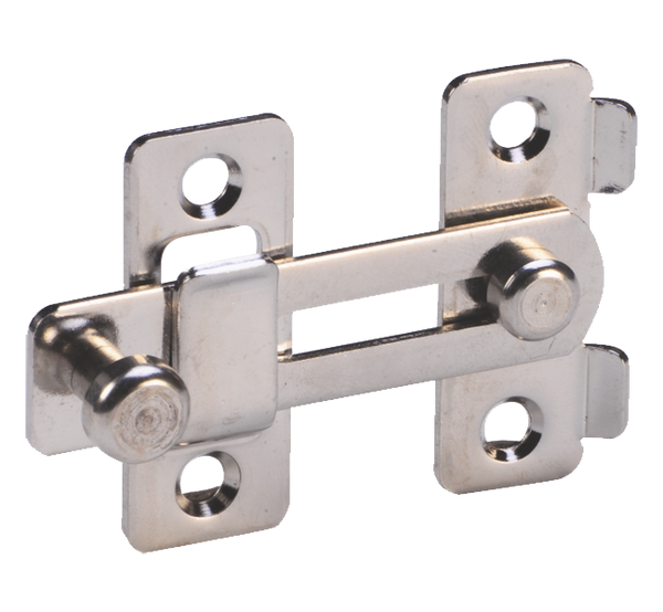
Lock having rotating bolt.
Available in Standard and Threaded mounting models. 90° rotary cam movement, convertible.
Key removable in locked and unlocked positions.
Zinc alloy die-cast.
Up to 1000 possible combinations - MCL2-25
| Model | Code | Combination | Finish |
| Cam Lock - Standard | MCL1-22 | Nickel Plated | |
| Cam Lock - Threaded 16 mm | MCL2-16 | Nickel Plated | |
| Cam Lock - Threaded 25 mm | MCL2-25 | Up to 1000 possible combinations | Nickel Plated |
| Cam Lock - Threaded 30 mm | MCL2-30 | Nickel Plated |
Rs. 2,018.00
Rs. 144.00
Ebco click on hinge (1) HC (1) Set of 2 Pcs
Type - 1) Overlay (HC1 (I) )
2) Half overlay ( HC2 (I) )
3) Inset ( HC3 (I) )
Ideal for cabinet, flush door, shutter
Finish - Nickel Plated
Rs. 656.00

Rs. 656.00
Special Features:
Specification:
| Item | Code | Size | Finish |
| Combination Lock -Pedestal (16-20mm) | P-CLP4-18 | 16-20mm | AT |

Sold Out
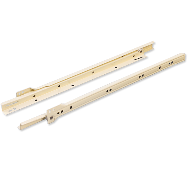
| Model | Code | Slide Length(mm) | Extension(mm) | Gap/Side(mm) | Max. Load(Kgs) | Finish |
| Computer Keyboard Slide | CKDS-35 | 350 | 200 | 20 | 35 | Zinc Plated White / Black |
| Model | Code | Slide Length(mm) | Extension(mm) | Max.Load(Kgs) | Finish |
| Computer Keyboard Slide - Eco (I) | CKSE-35-I | 350 | 250 | 12 | Zinc Plated White/Bla |
Sold Out
| Model | Code | Length in mm | Extension in mm | Finish |
| Powder Coated Black | ||||
| Keyboard Tray Full Extension - Soft Pad | KTS25FE | 250 | 260 |
Rs. 1,092.00
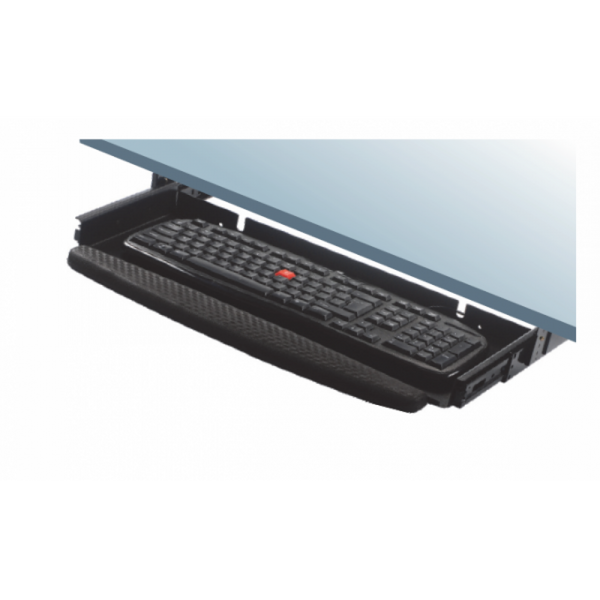
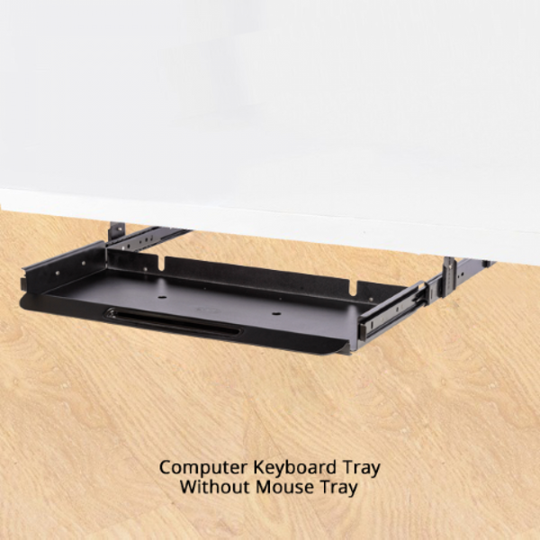
| Item | Type | Code Nos. | Finish |
| Computer Keyboard Tray | With Mouse Tray | KBT35M | Black Texture |
| Computer Keyboard Tray | Without Mouse Tray | KBT35 | Black Texture |
*If you have any specific question related to the product & if you want to buy Sold Out products, please contact us.
Assemble height adjustment brackets on to slides using M4 screw provided as in Fig. 1
2. Drill as per drilling diagram Fig. 2
3. Height adjustment bracket should be adjusted for desired height.
4. Screw the keyboard tray onto the table. Table should have minimum horizontal gap of 600mm.
5. Slide the keyboard tray out till it automatically latches.
6. To remove tray lift ltaches provided on each sides and pull as per Fig. 3.


Rs. 527.00
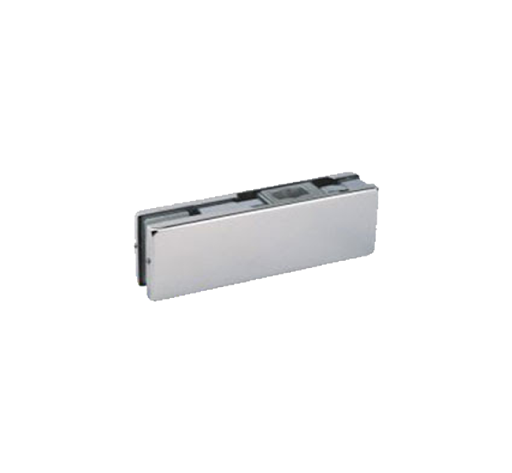
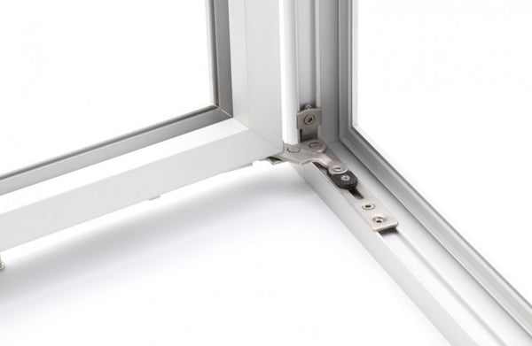
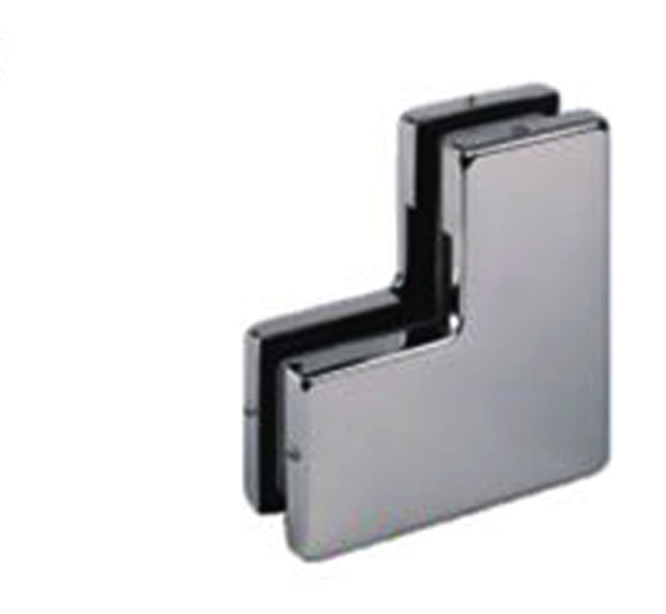
With a new bevelled groove. Used for aluminium windows with Euro Groove 1 (Frame) and Euro Groove 2 (Shutter
| Item | Code | Size | Finish |
| Concealed Corner Hinge side Hung - 80 (with New Bevelled Groove) | CCH-SH-80 | 2 mm | SS 304 |
| Concealed Corner Hinge side Hung - 120 (with New Bevelled Groove) | CCH-SH-120 | 3 mm | SS 304 |
Rs. 1,048.00
Rs. 764.00
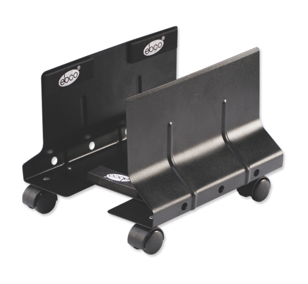
CPU Stand - ECO CPUS E1 Set of
C.P.U. Stand for storage of C.P.U. Unit just under the table.
This saves a lot of space in the table.
Vibration pad are installed for the safety of your CPU unit.
Width adjustment: 100-205 Max Load 12 kg

Rs. 12,800.00
Secure your home with the Ebco CREST I CR01 — an affordable smart digital door lock that delivers reliable security without compromise. Simple to use and built to last.
| Feature | Details |
|---|---|
| Access Modes | Fingerprint, RFID Card, Secure Password, Mobile App |
| Remote Control | WiFi-enabled with real-time alerts via Mobile App |
| Security | Single-Bolt, Anti Pry Alarm, Privacy Mode |
| Battery | 4 AA Alkaline batteries with low battery indication |
| Emergency Access | Emergency Key + Emergency Power Backup (USB) |
| Warranty | 2-Year Manufacturer Warranty |
| Parameter | Details |
|---|---|
| Item Code | DHDDLCR015ASA-BL |
| Finish | Black |
| Door Type | Wooden Door |
| Door Thickness | 35–90 mm |
| Backset | 50 mm |
| Dimensions (Internal) | 270(H) × 63(W) × 70(D) mm |
| Dimensions (External) | 270(H) × 63(W) × 70(D) mm |
| Access Type | Max Users |
|---|---|
| Admin | Up to 10 |
| Fingerprint | Up to 100 |
| Password | Up to 100 |
| Card | Up to 100 |
🎉 Flat 20% Off — Use Code FLAT20 at Checkout
Available exclusively at KnobsKart.com — India's premium hardware destination.

Rs. 14,500.00
Secure your home with the Ebco CREST I CR02 | CR03 — a semi-automatic smart digital door lock that delivers reliable security without compromise. Simple to use and built to last.
| Feature | Details |
|---|---|
| Access Modes | Fingerprint, NFC Card, Secure Password, Mobile App |
| Remote Control | WiFi-enabled with real-time alerts via Mobile App |
| Security | Tri-Bolt, Anti Pry Alarm, Privacy Mode |
| Battery | 4 AA Alkaline batteries with low battery indication |
| Emergency Access | Emergency Key + Emergency Power Backup (USB) |
| Warranty | 2-Year Manufacturer Warranty |
| Parameter | Details |
|---|---|
| Item Code | CR02: DHDDLCR025ASA-BL (Black) CR03: DHDDLCR035ASA-AT (Anthracite) |
| Door Type | Wooden Door |
| Door Thickness | 35–55 mm |
| Backset | 60 mm |
| Dimensions (Internal) | 293(H) × 155.2(W) × 67.2(D) mm |
| Dimensions (External) | 293(H) × 155.2(W) × 73(D) mm |
| Access Type | Max Users |
|---|---|
| General | Up to 290 |
| Admin | Up to 10 |
| Fingerprint | Up to 100 |
| Password + Card | Up to 200 |
🎉 Flat 20% Off — Use Code FLAT20 at Checkout
Available exclusively at KnobsKart.com — India's premium hardware destination.

Rs. 15,100.00
Secure your home with the Ebco CREST I CR04 — an affordable smart digital door lock that delivers reliable security without compromise. Simple to use and built to last.
| Feature | Details |
|---|---|
| Access Modes | Fingerprint, RFID Card, Secure Password, Mobile App |
| Remote Control | WiFi-enabled with real-time alerts via Mobile App |
| Security | Single-Bolt, Anti Pry Alarm, Privacy Mode |
| Battery | 4 AA Alkaline batteries with low battery indication |
| Emergency Access | Emergency Key + Emergency Power Backup (USB) |
| Warranty | 2-Year Manufacturer Warranty |
| Parameter | Details |
|---|---|
| Item Code | DHDDLCR045ASA-BL |
| Finish | Black |
| Door Type | Wooden Door |
| Door Thickness | 35–50 mm |
| Backset | 50 mm |
| Dimensions (Internal) | 420(H) × 75(W) × 41(D) mm |
| Dimensions (External) | 420(H) × 76(W) × 25(D) mm |
| Access Type | Max Users |
|---|---|
| Fingerprint | Up to 100 (Admin: 10) |
| Password | Up to 100 (Admin: 5) |
| Card | Up to 100 |
🎉 Flat 20% Off — Use Code FLAT20 at Checkout
Available exclusively at KnobsKart.com — India's premium hardware destination.
Rs. 1,775.00
Special Features:
Specifications:
| Item Code |
Body Size in mm |
Hold Open Facility | Fire Rated | Latching and Closing Speed Adjust Valve | Technical Parameter | |||
| L | W | H | Door Width | Weight | ||||
| DC 101 | 148 | 37 | 57 | Yes | Yes | Available | 600-800mm | 60kgs |
The steps of vertical installation
The standard installation
The template of the right hand pull side door vertical installation.
(The template of the left hand pull side door vertical installation is opposite of the template of the right hand pull side door vertical installation).
The reverse installation
The template of the left hand push side door vertical installation.
(The template of the right hand push side door vertical installation is opposite of the template of the left hand push side door vertical installation).
The steps of parallel installation
Adjust the speed of the door closer by:-
The parallel installation
The template of the right hand push side door parallel installation
(The template of the left hand push side door parallel installation is opposite of the template of the right and push side door parallel installation)
Notices.
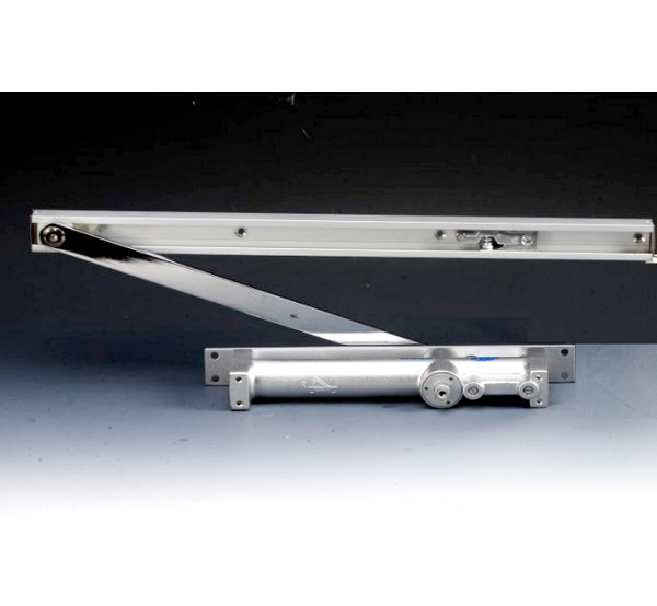
Rs. 5,166.00
Special Features:
Specifications:
| Item Code |
Body Size in mm |
Hold Open Facility | Fire Rated | Latching and Closing Speed Adjust Valve | Technical Parameter | |||
| L | W | H | Door Width | Weight | ||||
| DC 1001 | - | - | - | Yes | Yes | Available | 950mm | 65kg |
Rs. 5,822.00
Special Features:
Specifications:
| Item Code |
Body Size in mm |
Hold Open Facility | Fire Rated | Latching and Closing Speed Adjust Valve | Technical Parameter | |||
| L | W | H | Door Width | Weight | ||||
| DC 1002 | - | - | - | Yes | Yes | Available | 950mm | 85kg |
Rs. 109.00
Made out of SS 304.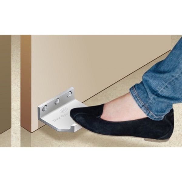
Subscribe to our newsletter and always be the first to hear about what is happening.